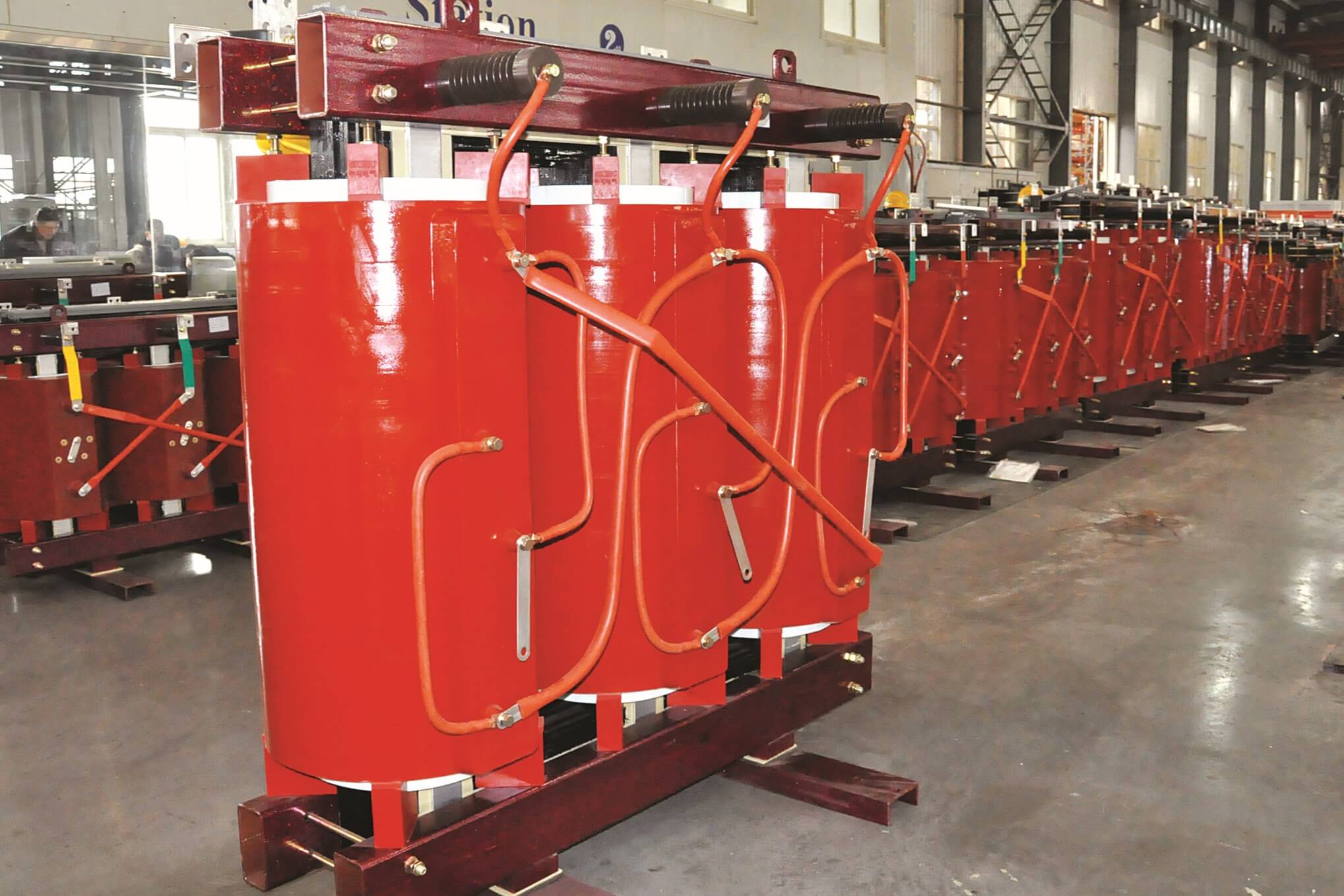
![Cast Resin Transformer]()
Basic Parameters
Standard: IEC60076
Voltage Range: 1.1~35kv
Rated Capacity: 100-25000kVA
Core material: Silicon Steel
Insulation Temperature: 150℃/180℃
Cooling way: AN/AF/AFWF
Impedance: 4-8%
Vector group: Dyn11/Yyn0 / others on request
Tapping Range: ±2*2.5%/±5%
Working temperature: -20℃~60℃
Key Product Features
Exceptional Reliability & Low Losses
Optimized design delivers low partial discharge (PD), minimal noise (enhanced by a nano-paint self-leveling process), and very low loss operation, translating to higher energy efficiency and lower total cost of ownership.
Superior Environmental Adaptability
Outstanding moisture-resistant performance, capable of stable operation in high-humidity environments, including 100% relative humidity.
Robust Short-Circuit Design
Designed for superior mechanical strength and excellent resistance to dynamic and thermal stresses during a short circuit. Passed stringent type tests of withstanding 150% overload in forced air-cooling conditions.
International Quality Compliance
One of the earliest manufacturers in China to pass the rigorous KEMA E2, C2, and F1 tests for environmental, climatic, and fire behavior—critical certifications for international market acceptance.
Advanced Simulation-Driven Design
Utilizes electric field, temperature field, and magnetic field simulation analysis to optimize core and coil design for maximum performance and longevity.
Smart Grid Ready
Provides intelligent transformer solutions, including real-time online big data cloud diagnosis and monitoring for enhanced operational control and predictive maintenance.
Technical Series Overview
10kv Series
Customization: Supports customization of parameters exceeding standard IEC requirements.
Safety & Fire Protection: Inherently safe, flame-retardant, self-extinguishing, and pollution-free operation. Ideal for installation in critical load centers where fire safety is paramount.
Maintenance & Costs: Maintenance-free design and easy installation result in low overall operating and life-cycle costs.
Robustness: Features low temperature rise, high structural stability, and strong seismic resistance for reliable long-term service.
Scope of Application: Excellent environmental adaptability suitable for installations with large seasonal load fluctuations or intermittent overload requirements (e.g., commercial buildings, hospitals, and light industrial facilities).
35kV Series
Short Circuit Withstand: Winding structure optimized through dynamic thermal stability simulation analysis, resulting in high transformer short circuit design strength.
Overload Capacity: Capable of long-term reliable operation, with a strong overload capacity even without forced air cooling (AF).
Impact Resistance: Careful distribution of winding capacitance ensures strong resistance to lightning and switching impulse voltages.
Fire Safety: Flame-retardant and self-extinguishing, emitting no toxic gases during combustion.
Scope of Application: High-density power demand locations like densely populated urban substations, large-scale data centers, and heavy industrial facilities with limited space.
Core Components & Engineering
![transformer core]()
Transformer Core
Material & Design: Constructed from grain-oriented and cold-rolled silicon steel plates with high magnetic conductivity to minimize stray flux losses and ensure high efficiency.
Joint Structure: All laminations are precisely lap-jointed at 45°with a 7-stepping seam to reduce no-load current and noise.
Protection: The surface is coated with a special moisture-proof and rust-proof coating, providing effective anti-oxidation and anti-corrosion protection while further reducing acoustic noise.
![Hedrich vacuum casting tank]()
High-voltage (HV) Coil
Construction: The HV copper coil features a multi-layer segmented cylindrical structure.
Encapsulation: Coils are reinforced with glass fiber and pressure cast under vacuum (1-3 bar) using high-quality epoxy resin (specifically formulated for electrical insulation) via advanced Hedrich vacuum casting equipment.
Benefits: This superior cast coil transformer construction ensures high mechanical strength and reliable insulation, guaranteeing a partial discharge (PD) level below $5\text{PC}$—significantly lower than typical standards.
Low-voltage (LV) Coil
Winding: The LV coil is made of high-quality copper foil conductor, precisely wound on an automatic foil winding machine.
Quality Control: Utilizes advanced technologies like the "foil wire hydraulic energy-saving tension winding device" and high-precision ±0.5 detection, along with advanced argon arc welding, to ensure superior and consistent coil winding quality, which is critical for short-circuit design integrity.
![winding machine]()
![LV Coil Finishing]()
Temperature Monitoring & Protection
Sensing: Temperature is precisely detected and controlled via a PT thermistor embedded in the low-voltage coil.
Interface: Outputs digital signals through the RS232/485 communication interface for remote monitoring and integration with customer management systems.
Functions:
Displays real-time temperature values of all three-phase windings.
Displays the temperature value of the hottest phase winding.
Provides overtemperature alarm and automatic trip functions.
Manages sound/light alarms and automatic fan start/stop for cooling system management.
Cooling System
Natural Air Cooling (AN): Under normal conditions, the transformer can continuously output 100% of its rated capacity.
Forced Air Cooling (AF): Activation of the fans allows the transformer to increase capacity by 50% to handle emergency or intermittent overload operations.
Note: Due to the significant increase in load loss and impedance resistance, long-term continuous overload operation using forced air cooling (AF) is not recommended
![transformer enclosure]()
Transformer Enclosure
Protection Levels: Available in various IP ratings, including standard IP20, IP23, IP32, IP54, and customized levels.
Materials: Constructed from durable materials such as iron, stainless steel, and aluminum alloy.
Design: Designed as an assembly structure for easy disassembly and transport to the installation site. The removable top cover ensures convenient access for inspection and maintenance.
Technical Parameters
We can produce SC(B)10-100~2500/10 up to SC(B)24-100~2500/10
SC(B)10-100~2500/10 |
Rated High Voltage:10(10.5,11,6.6,6.3,6)kV, Rated Low Voltage:0.4kV |
Vector Group: Dyn11or Yyn0, Tap Range:±2*2.5% |
Model | Impedance % | No Load Loss (W) | (75℃)Load Loss (W) | No Load Current % | Noise Level (dB) |
SC(B)10-100/10 | 4 | 400 | 1371 | 0.7 | 42 |
SC(B)10-125/10 | 4 | 470 | 1616 | 0.7 | 43 |
SC(B)10-160/10 | 4 | 540 | 1860 | 0.7 | 43 |
SC(B)10-200/10 | 4 | 620 | 2209 | 0.7 | 43 |
SC(B)10-250/10 | 4 | 720 | 2410 | 0.7 | 43 |
SC(B)10-315/10 | 4 | 880 | 3030 | 0.7 | 45 |
SC(B)10-400/10 | 4 | 980 | 3484 | 0.7 | 45 |
SC(B)10-500/10 | 4 | 1160 | 4260 | 0.6 | 46 |
SC(B)10-630/10 | 4 | 1340 | 5134 | 0.6 | 46 |
SC(B)10-630/10 | 6 | 1300 | 5200 | 0.6 | 48 |
SC(B)10-800/10 | 6 | 1520 | 6020 | 0.5 | 49 |
SC(B)10-1000/10 | 6 | 1770 | 7090 | 0.4 | 50 |
SC(B)10-1250/10 | 6 | 2090 | 8460 | 0.4 | 51 |
SC(B)10-1600/10 | 6 | 2450 | 10240 | 0.3 | 51 |
SC(B)10-2000/10 | 6 | 3050 | 12600 | 0.3 | 52 |
SC(B)10-2500/10 | 6 | 3600 | 15000 | 0.3 | 53 |
SCB10-1600/10 | 8 | 2450 | 11263 | 0.3 | 51 |
SCB10-2000/10 | 8 | 3035 | 13882 | 0.3 | 52 |
SCB10-2500/10 | 8 | 3600 | 16414 | 0.3 | 53 |
SC(B)18-100~2500/10 |
Rated High Voltage:10(10.5,11,6.6,6.3,6)kV, Rated Low Voltage:0.4kV |
Vector Group: Dyn11or Yyn0, Tap Range:±2*2.5% |
Model | Impedance % | No Load Loss (W) | (75℃)Load Loss (W) | No Load Current % | Noise Level (dB) |
SC(B)18-100/10 | 4 | 230 | 1240 | 0.7 | 42 |
SC(B)18-125/10 | 4 | 270 | 1450 | 0.7 | 43 |
SC(B)18-160/10 | 4 | 310 | 1670 | 0.7 | 43 |
SC(B)18-200/10 | 4 | 360 | 1990 | 0.7 | 43 |
SC(B)18-250/10 | 4 | 415 | 2170 | 0.7 | 43 |
SC(B)18-315/10 | 4 | 510 | 2730 | 0.7 | 45 |
SC(B)18-400/10 | 4 | 570 | 3140 | 0.7 | 45 |
SC(B)18-500/10 | 4 | 670 | 3830 | 0.6 | 46 |
SC(B)18-630/10 | 4 | 775 | 4610 | 0.6 | 46 |
SC(B)18-630/10 | 6 | 750 | 4690 | 0.6 | 48 |
SC(B)18-800/10 | 6 | 875 | 5470 | 0.5 | 49 |
SC(B)18-1000/10 | 6 | 1020 | 6430 | 0.4 | 50 |
SC(B)18-1250/10 | 6 | 1205 | 7610 | 0.4 | 51 |
SC(B)18-1600/10 | 6 | 1415 | 9230 | 0.3 | 51 |
SC(B)18-2000/10 | 6 | 1760 | 11420 | 0.3 | 52 |
SC(B)10-2500/10 | 6 | 2080 | 13540 | 0.3 | 53 |
SC(B)10-1600/10 | 8 | 1415 | 10160 | 0.3 | 51 |
SC(B)10-2000/10 | 8 | 1760 | 12530 | 0.3 | 52 |
SC(B)10-2500/10 | 8 | 2080 | 14830 | 0.3 | 53 |
SC(B)10-200~2500/20 |
Rated High Voltage:20(10.5,11,6.6,6.3,6)kV, Rated Low Voltage:0.4kV |
Vector Group: Dyn11or Yyn0, Tap Range:±2*2.5% Isulation Level: LI 125 AC 50/ LI AC 3 |
Model | Impedance % | No Load Loss (W) | (75℃)Load Loss (W) | No Load Current % | Noise Level (dB) |
SC(B)10-200/20 | 6 | 730 | 2565 | 1.0 | 47 |
SC(B)10-250/20 | 6 | 840 | 2985 | 1.0 | 47
|
SC(B)10-315/20 | 6 | 970 | 3560 | 0.9 | 48 |
SC(B)10-400/20 | 6 | 1150 | 4225 | 0.8 | 48 |
SC(B)10-500/20 | 6 | 1350 | 5055 | 0.8 | 50 |
SC(B)10-630/20 | 6 | 1530 | 5970 | 0.7 | 50 |
SC(B)10-800/20 | 6 | 1750 | 7210 | 0.6 | 51 |
SC(B)10-1000/20 | 6 | 2070 | 8540 | 0.5 | 52 |
SC(B)10-1250/20 | 6 | 2380 | 10040 | 0.5 | 52 |
SC(B)10-1600/20 | 6 | 2790 | 12050 | 0.4 | 53 |
SC(B)10-2000/20 | 6 | 3240 | 14230 | 0.4 | 53 |
SC(B)10-2500/20 | 6 | 3870 | 16850 | 0.3 | 54 |
SC11-800~25000/35 |
Rated High Voltage:35(38.5,37.5,36.5,33)kV, Rated Low Voltage:10.5(11,6.0,6.3,3.15)kV |
Vector Group: Yd11, YNd11, or Dyn11, Tap Range:±2*2.5% |
Model | Impedance % | No Load Loss (W) | (75℃)Load Loss (W) | No Load Current % | Noise Level (dB) |
SC11-800/35 | 6 | 2025 | 9400 | 0.6 | 50 |
SC11-1000/35 | 6 | 2400 | 10900 | 0.6 | 50 |
SC11-1250/35 | 6 | 2815 | 12900 | 0.5 | 50 |
SC11-1600/35 | 6 | 3320 | 15400 | 0.5 | 50 |
SC11-2000/35 | 7 | 3805 | 18200 | 0.45 | 52 |
SC11-2500/35 | 7 | 4370 | 21800 | 0.45 | 52 |
SC11-3150/35 | 8 | 5425 | 24500 | 0.4 | 53 |
SC11-4000/35 | 8 | 6315 | 29400 | 0.4 | 53 |
SC11-5000/35 | 8 | 7530 | 34900 | 0.35 | 54 |
SC11-6300/35 | 8 | 8910 | 40800 | 0.35 | 54 |
SC11-8000/35 | 9 | 10170 | 46000 | 0.3 | 56 |
SC11-10000/35 | 9 | 11610 | 55500 | 0.25 | 60 |
SC11-12500/35 | 9 | 14130 | 64600 | 0.2 | 60 |
SC11-16000/35 | 9 | 17370 | 76000 | 0.2 | 62 |
SC11-20000/35 | 10 | 20610 | 85500 | 0.2 | 62 |
SC11-25000/35 | 10 | 24390 | 101000 | 0.2 | 64 |
![cast resin transformer workshop]()
![testing center]()
![35kV Cast Resin Transformer]()
![Double-split transformer]()
![Cast Resin Transformer For Energy Storage System]()
![Double Voltage Cast Resin Transformer]()